Website powered by

Maya Python API: Getting/Setting Skin Weights

Tutorial / 22 April 2019

The Maya API is an incredibly useful tool to have in your toolbelt as a td. With the data it gives you access to, you can do operations that would be slow, if not impossible, to do with MEL or maya.cmds


In this post, I'll document how I get and set Skin Cluster weights so as to do operations like influence pruning, smoothing, copy/paste average, and more. 

The basic structure of these scripts is all the same. You get the selected components, find the skinCluster they belong to, get its influence and weight list, do something to change that list, and then set the weights again. I'm using the Python API for this, but if you know C++ and how to compile it with Maya you are at a huge speed advantage, especially when iterating over a ton of components. 

API Reference

Getting the Selection

The first thing I usually do is store the original selection in a MSelectionList object so that we can reset the selection to that at the very end. This helps keep the user's workflow (generally mine) less interrupted by constant object/component level switching. 

    original_sel = om.MSelectionList()
    om.MGlobal.getActiveSelectionList(original_sel)

"om" is my chosen abbreviation for the maya.OpenMaya module. 


Getting the Selected Mesh and Components

The next step is to a quick way to make sure you're iterating over vertices. We do this since all the data we'll be looking for is stored at a vertex level. In this case, we're only going to do operations over one mesh. If you wanted to do this over multiple meshes at once, you'd use a MItSelectionList object. 

    cmds.select(cmds.polyListComponentConversion(toVertex=True))


    # get the selected mesh and components
    sel = om.MSelectionList()
    om.MGlobal.getActiveSelectionList(sel)


    if not sel.length():
      return


    selected_components = om.MObject()
    dag = om.MDagPath()
    sel.getDagPath(0, dag, selected_components)


    dag.extendToShape()


    if dag.apiType() != 296:
      om.MGlobal.displayError("Selection must be a polygon mesh.")
      return

Above, I'm using a handy maya.cmds function to quickly convert our selections to vertices. I do this after I store the original selection and before I store it in our selection list since I want that selection list to hold vertices. If I didn't, it wouldn't be able to derive the correct vertices from the edges/faces/objects I had selected. 

If there isn't anything selected, I get out of the function. Otherwise I get the MDagPath object of the selection as well as any components on it that are currently selected. Then I do a check to see if the apiType of its shape node is 296, which is the type for polygonal meshes. This iterator isn't designed for anything except skinClusters on polygons. That's what I'm almost always using anyways. 


Getting the SkinCluster's Name and MObject

Next I use a handy function that again utilizes some quick maya.cmds functions to get us data quicker. If you're using the Maya Python API, you have the advantage of also using maya.cmds as you work. Don't kill yourself over iterating up a DG if you can do the same thing in one line of maya.cmds. If speed is your concern, don't use maya.cmds in loops that iterate over thousands of components. 

def getSkinCluster(self, dag):
    """A convenience function for finding the skinCluster deforming a mesh.

    params:
      dag (MDagPath): A MDagPath for the mesh we want to investigate. 
    """

    # useful one-liner for finding a skinCluster on a mesh
    skin_cluster = cmds.ls(cmds.listHistory(dag.fullPathName()), type="skinCluster")

    if len(skin_cluster) > 0:
      # get the MObject for that skinCluster node if there is one
      sel = om.MSelectionList()
      sel.add(skin_cluster[0])
      skin_cluster_obj = om.MObject()
      sel.getDependNode(0, skin_cluster_obj)

      return skin_cluster[0], skin_cluster_obj

    else:
      raise RuntimeError("Selected mesh has no skinCluster")


The line cmds.ls(cmds.listHistory(dag.fullPathName()), type="skinCluster")  is an especially useful one-liner that I use ALL THE TIME. I'm using the ls command to filter any skinCluster type objects out of an object's history list. If there is a length to that list, then one exists. I'm then using MSelectionList to get the MObject from that skin cluster node. 


Getting the Skin Weights

Now that we have the MObject for our skinCluster we can make our MFnSkinCluster object and get access to all the handy functions it provides. Much of what I do next is gathering the information required to get and set the weights for our skinCluster. One of those is an MDagPathArray of the influence objects (joints) that influence our mesh. The other is a pointer to an unsigned integer object that holds the amount of influence objects on the skinCluster. The last is an MIntArray that basically just goes from 0 to 1 minus the amount of influence objects. Again, all just information we need to pass to MFnSkinCluster.getWeights, but once you do it right, you don't really need to write it again. 

    # doing this can speed up iteration and also allows you to undo all of this
    cmds.skinPercent(skin_cluster, pruneWeights=0.005)

    mFnSkinCluster = omAnim.MFnSkinCluster(skin_cluster_obj)

    inf_objects = om.MDagPathArray()
    # returns a list of the DagPaths of the joints affecting the mesh
    mFnSkinCluster.influenceObjects(inf_objects)
    inf_count_util = om.MScriptUtil(inf_objects.length())

    # c++ utility needed for the get/set weights functions
    inf_count_ptr = inf_count_util.asUintPtr()
    inf_count = inf_count_util.asInt()
    influence_indices = om.MIntArray()

    # create an MIntArray that just counts from 0 to inf_count
    for i in range(0, inf_count):
      influence_indices.append(i)

    old_weights = om.MDoubleArray()
    # don't use the selected_components MObject we made since we want to get the weights for each vertex 
    # on this mesh, not just the selected one
    empty_object = om.MObject()
    mFnSkinCluster.getWeights(dag, empty_object, old_weights, inf_count_ptr)

    # new_weights just starts as a copy of old_weights
    new_weights = om.MDoubleArray(old_weights)


Iterating and DOING STUFF

Now we're ready to actually DO STUFF to the weight list we got. That weight list is kind of strange at first and can be tricky to work with. It's a one-dimensional list of length (influence_count * component_count) so that the "weights" for one vertex is at the subset weight_list[this_vert_weight_index: this_vert_weight_index + inf_count]. 

So now we iterate over the selected components using a MItMeshVertex object, which again gives us a TON of information at a vertex level like its index (which will correspond to the correct index in the weight list), its neighbors, and its normal vector. If you needed more information or needed to do stuff like raycasting, you can make a MFnMesh object outside of the iterator and get even more information from your mesh. Pretty nice, huh. 

    # iterate over the selected verts
    itVerts = om.MItMeshVertex(dag, selected_components)
    
    while not itVerts.isDone():
      this_vert_weight_index = itVerts.index() * inf_count
      vert_weights = list(new_weights[this_vert_weight_index: this_vert_weight_index + inf_count])

      # makes the weights for the closest vertex equal to the outer vertex
      new_weights[this_vert_weight_index: this_vert_weight_index + inf_count] = SOME AWESOME FUNCTION

      itVerts.next()

    # set weights all at once
    mFnSkinCluster.setWeights(dag, empty_object, influence_indices, new_weights, True, old_weights)

    om.MGlobal.setActiveSelectionList(original_sel)
Technical Direction for Rigging and Animation

Tutorial / 23 February 2019

This post is an excerpt from a larger essay I've written on Digital Character pipelines.

Rigging

As with Surfacing, Rigging, home of Character Technical Directors like me, is another highly technical department that is difficult to give quick advice on. There are, however, certain workflow tips that I think could be universally helpful to an aspiring Character TD. If you do not know, Character TDs are responsible for creating the skeleton of the character, defining how that skeleton will move the mesh, and making control systems to make animating the skeleton as friendly as possible. They also write scripts and pipeline tools to make the technical side of computer animation as streamlined as possible. Skeletons are hand-placed and are often shared across similar character build types for efficiency. When a character is being developed, the entire motion system for the character will almost consistently be evolving based on animation and shot-specific needs. For that reason, rigs, the motion systems that drive the skeleton, are usually scripted to make the complex process of setting them up faster, consistent, and flexible. 

As stated previously, rigging can begin in some of the earliest stages of a character’s look development. If, for example, you know from the beginning your character is going to be a standard biped, you could pretty quickly narrow in on the basic proportions and volumes of the character and apply your rig to it. The animator can then reference in that rig and begin to animate on it. As long as attributes like the names, orientation, and rotation orders of the controls stay consistent through a rig’s development, animation generally transfers pretty well when the rig (and reference) is updated. More on this later. 

As the model gets updated, the rigger can replace the outdated portions of the character with the more final versions of the mesh. They can do this transfer efficiently using the CopySkinWeights tool or a custom extension of it. Art updates like adding UVs or adjusting the model happen on an almost daily basis in game and film production and are not a huge deal to implement. As long as the location of the character’s joints stays the same and volumes don’t change too much, a rig can be developed for a character from a very early stage. Faces, as stated before, are generally much more difficult to apply art updates to and should be as dialed-in as possible before rigging is begun (linear development). 

Sending a rig to a game engine can be a pretty confusing process at first. The important thing to understand is that all the engine accepts from rigs are its mesh, joints, skinning, and keyframes. As a best practice, the mesh and joints should be children of a single node. 


Something like: 

Character
> char_geo (can be a grouped if more than one mesh)
> root (the skeleton of the rig)
  > cog
      …


Notice that the hierarchy there contains none of the rig components or constraints. All it has are the joints plus the meshes they are bound to and nothing else. Therefore if you have a regular rig and you want to export a clean fbx to an engine like Unreal, these are the steps you’d take:

  • Select all of the bind joints and do Edit>Keys>BakeSimulation 

    • Doing this ensures that when we delete the rig, the transform values on the joints will stay the same.

  • Delete everything in the rig other than the final bind geometry and joints

  • Select the whole hierarchy and ExportSelection as an FBX

    • If you’re only exporting the fbx as a skelemesh (no animation) then uncheck Animation

    • FBX version 2014/15 works pretty consistently in my experience.

FBX is basically a filetype kind of like an obj except that it can hold a lot of extra data like animation, joints, cameras, etc...


Animation

Animating a complex character in a parallel pipeline is as necessary as it is practical. With render-time polycounts for characters constantly increasing, the necessity for “lite” versions of characters–with a model density that can give real-time playback speed–has become commonplace. Many animators may already be familiar with this type of development as many student rigs give options for “proxy”, “low” and “high” resolution versions of the model to increase manipulation speeds. These different model resolutions are useful at different parts in the animation process: “proxy” for blocking, “low” for breakdowns, and “high” for polish. As long as the volumes and proportions of those representations are the same, animation can be transferred up in model resolution without much artistic issue. 


With this in mind, you can really start to see how little an animator really needs to start progress on a shot. A “proxy” version of a character model can be created very early in the design process as long as the character’s proportions and volumes have been somewhat established. As the animator works, she uses Maya Referencing to load the rig into her scene. This enables the Character TD to work alongside the animator to pass them updated geometry as it comes down the pipeline. Furthermore, it enables them to find the best possible rig for that character as the animator can critique details like joint placement, skinning, and rig features. If one uses referencing while animating, updates like these can be pushed to the rig without much change to the animator’s work. 

There are, however, a few changes that will pose a real technical challenge to keeping the animator’s animation how it was established. These problematic changes can include:


Proportions. Animations done using IK controls, which are based on Translation, will likely now be broken. Imagine an animation where a character reaches to drink from a cup in IK but the arm is now 20% shorter. What used to be an acceptable reach might now fully extend the arm and the hand may not even be able to reach the cup. This is a simple example of a common problem in retargeting motion capture animation across a variety of differently-sized rigs. Insomniac Games’ Lead Character TD Adalbert Kinsey gave a great GDC presentation on how they achieved this technical hurdle in their game Sunset Overdrive.


Orientation and Rotate Order. This is a big one and should be figured out as early as possible in a rig’s parallel development as there is not much opportunity for clean fixing here. The Orientation of a control refers to it's 3D axis of orientation in local space. Changing this could mean, for example, that an animation that used to twist a joint could now be bending it. Clearly, as that multiplies up the many controls in a rig, this would really break an animation. “Maya” does not understand your intention when you animate something. 

Changing the Rotate Order of a control is a more technical issue as it delves into the 3D math behind rotations, but for any riggers out there, just don’t do this unless absolutely necessary. Cleanly establish it early on.


Volumes. This is closely related to the kinds of issues that occur when changing the proportions of a character. Besides from the obvious artistic issues with transferring an animation from a heavier to a lighter character or vice versa, there will be issues with intersecting volumes. This doesn’t just refer to the body type of a character: if an accessory is added that drastically affects a character’s range of motion, animation will, again, have to be checked. 

As stated before, certain elements of a character’s rig are best developed in certain ways. While body systems are much more flexible in their development, facial rigs are much more touchy in the kinds of technical changes that can be made during their development. 


FACS Rigs: When animating on a work-in-progress FACS rig, it is a good idea to hold off on using tweaker controls for as long as possible. For context, a FACS rig is one based off of Paul Ekman’s Facial Action Coding System. Rigs built in this way break up expressions into their many muscular parts that the animator can drive using attributes. These shapes are best made in collaboration with the modeler, rigger, and animator, and the important thing to recognize is that they can be changed.

As a layer of finesse over the facial setup, what I call tweaker controls are put in to allow the animator to shape the facial shapes to their needs. However, if these controls are used too early on in development to fix unappealing facial shapes created by the FACS rig, it becomes very difficult for the animation done on the face to stay correct. 

For example, if the rigger made a Jaw_Down shape that needs work but the animator animated to the bad shape, the shape will always be wrong. But if the animator collaborated with the rigger and showed them the shape they generally want the Jaw_Down slider to make, the better shape can be baked into the rig itself and the animator will no longer need to animate around it. 

These kinds of situations come up a lot, and communication here is key. If some behavior of a rig is unappealing, it is always preferable to communicate that to a rigger and see if the problem can be fixed. 

Script Distribution using Maya Modules

General / 20 April 2018

Hi everyone!

As a TD, part of your job is to be able to create and distribute tools to the artists on your team. Sometimes, those artists may not be as tech-savvy as your average TD, and so part of the challenge is coming up with an easy way to distribute scripts and keep those scripts updated as you make changes to them.

Enter the magical ancient world of Maya’s module workflow.

In short, Maya’s module system allows scripts to be held in folders outside of the \user\maya\scripts folder. The magic of that is that you can thus put those scripts in a folder that’s shared over a network or cloud drive, which would allow for everyone on the team to be on the same page.

Here’s what you need to do:

Say you have a python script in the directory D:\sharedFolder\myScript.py

What you need to do is create a folder above that that will hold the entire module.

D:\sharedFolder\myModule\myScript.py

Then, you need to create a folder in there called “scripts” just like maya’s “scripts” folder and put in it all of the scripts you want to have shared. You could also do the same with plug-ins, icons, prefs… It’s essentially mirrors the \user\maya directory structure.

So! now you have D:\sharedFolder\myModule\scripts\myScript.py

And you’re almost set! Now what you need to do is in your \user\maya\modules folder, you need to create a type of file called a .mod file. This file will be used by maya to link the folder on our desktop to your maya’s path.

Just to get you started, the most basic syntax for a mod file is:

+ [module name] [version number] [full path to module folder]

for example:

+ myModule 1.0 D:\sharedFolder\myModule

Now, if you restart Maya and try to import myScript, everything should work as expected.

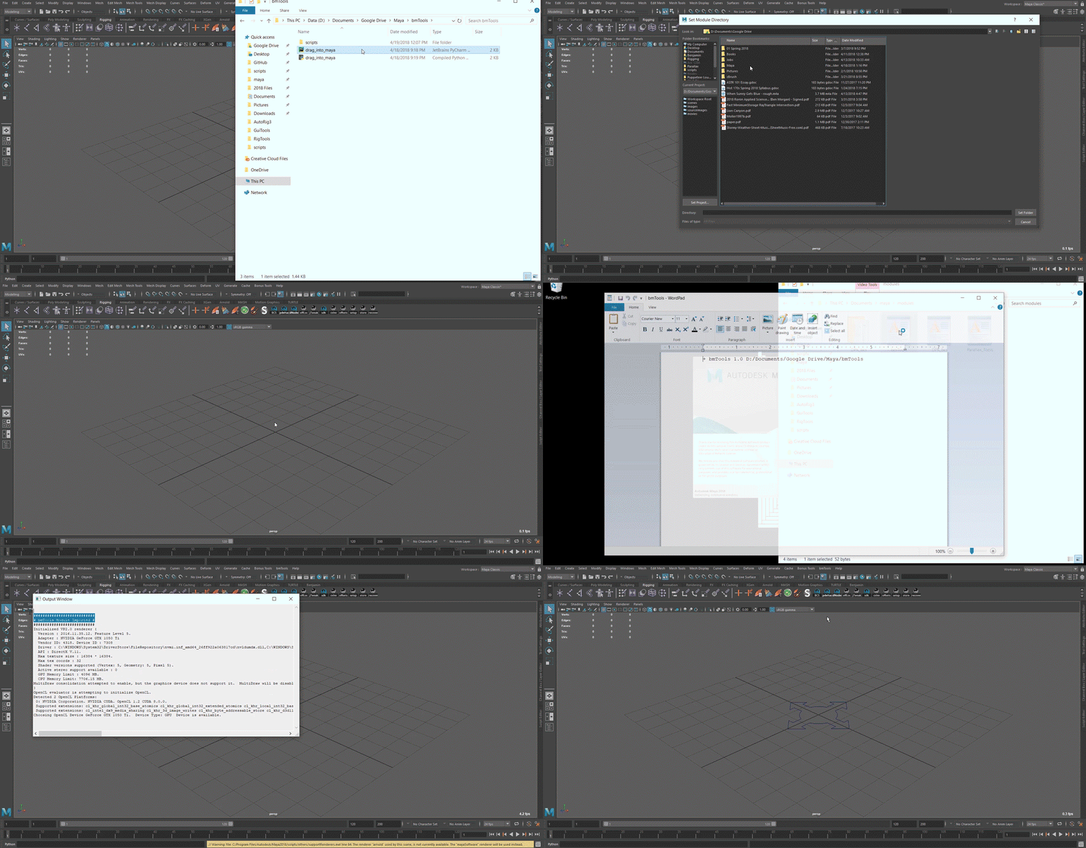
This kind of workflow, however, isn’t very animator friendly. That’s why I created a much quicker install method for installing a module.

  1. Download the module or add the shared folder to you shared drive.
  2. Drag a script called “drag_into_maya.py” into Maya and simply browse to confirm the module file’s location.
  3. Restart Maya and you’re done.

All I’m doing in that “drag_into_maya” python file is opening up a file dialog at the location of that python file, which should already be in the module package. I then write a .mod file into the “userAppDir” path ‘s module folder.

That’s it! Once you start looking into this, you’ll realize tools like the BCS and SHAPES are already being distributed via modules. I never really thought twice about modules before but this is honestly a game changer for my workflow. Thanks Rik, my coworker on a freelance project I’m on right now, for introducing me to this

Ben

More resources

Vector-Based Wheel Rigging

General / 07 March 2018

Hey everyone!

First of all, I’d like to start with announcing I’ll be a Character TD intern this summer at Insomniac Games! I’m so excited for this opportunity!

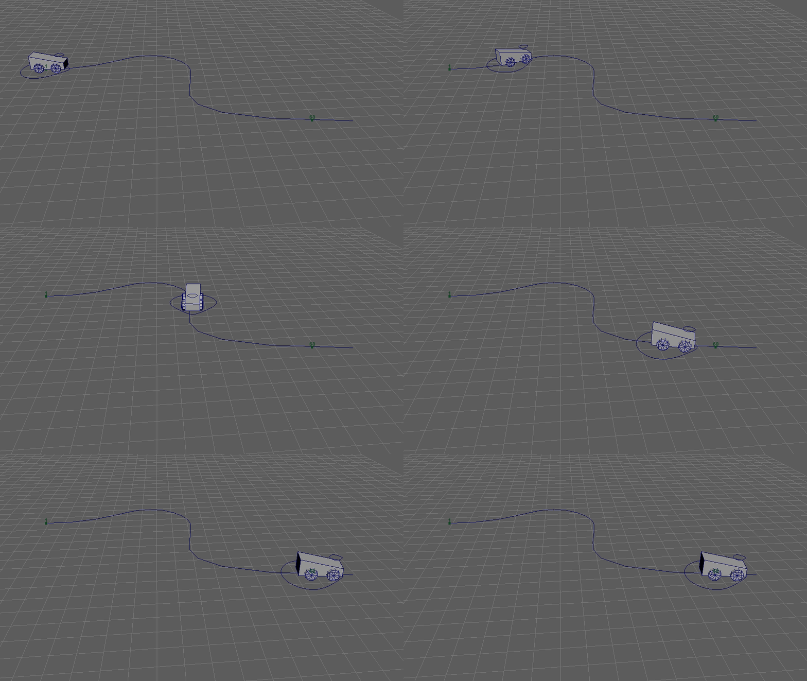
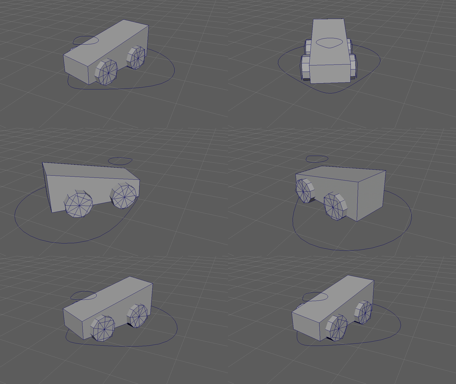
Anyways, I’ve been working on a lot lately, partly for the Puppeteer Lounge and partly for just regular university stuff, but in my free time I’ve been chipping away at a car solution in Maya.

Wheel Rotation

As a high school geometry refresher, in order to do a full 360 degree rotation, a wheel must travel a distance equal to Pi times its diameter, or C = Pi*D.  Traditional Maya wheel setups will use a simple set-driven-key approach to get things done. For example, for a wheel with diameter 2, you’d go Tau units (6.283) forward on the axis and have that drive a 360 degree rotation on the wheels. That can work for a basic setup, but you’ll still get a lot of wheel sliding since it’s only a one-dimensional driver.

A better way, I found, is to use a vector-based approach. I started with this youtube video as a starting point, but I found some problems with it, including confusing equations and variable names and also the fact that his technique for dot product doesn’t account for the wheel’s individual ry control. Either way, I knew I had to figure this out on my own to figure this out.

Vector Magnitude

The magnitude of a vector is equal to the square root of the sum its squared contents. In simpler words, it’s like the quadratic formula but for n dimensions. So magnitude is a scalar (number) that comes from a vector (“array”) and can be used as distance.

Therefore, at each frame, I knew I’d need to know the previous location and the current location as a vector. This was done using empty group nodes that I parented to a top level, “static” node (could be an XTR group in a rig). This transform node’s job is simply to store the previous frame’s location.

vector $wheel_old_vector = `xform -q -t -ws “wheel_cc_old_vector”`;

I then get the wheel’s current location:

vector $wheel_vector = `xform -q -t -ws “wheel_cc_pos_vector”`;

The current vector – previous vector gives us the movement vector from the previous to the current location, (I remember this as A-B gives B to A). The magnitude of this is the distance traveled.

vector $translate_vector = ($wheel_vector – $wheel_old_vector);

float $distance = mag($translate_vector);

At this point, we know the distance traveled and can calculate from that the rotation that we need to do ( 360 * distance / (Tau*radius) ). However, this doesn’t account for forward and backwards movement and for the lessened rotation that occurs when the direction of motion is oblique to the angle of the wheels.

Wheel Direction

I therefore added two other empty transform nodes to calculate the direction of the wheel. The first was just parented below the “move” control for the wheel and projected onto the zx plane, and the other is set as follows:

matchTransform wheel_cc_forward_vector wheel_cc_pos_vector;
xform -os -r -t 1 0 0 wheel_cc_forward_vector; 

So I’m matching the rotation and translation of the forward vector to the wheel vector and then going forward in object space from there. (I’m determining +as the forward direction here). From that, we get the vector:

vector $wheel_dir_vector = ($forward_vector – $wheel_vector);

This vector “points” in the direction of the wheel.

Vector dot products

Okay, I have to be honest. I had a pretty traditional Linear Algebra professor and I never really understood how dot products were related to cosine. I understood the dot product could give orthogonality and also if two vectors are pointing in similar directions, but cosine? What?

Well, you just have to normalize them, and it all makes sense.

v1 = [1,0,0]     v2 = [0,1,0]        << two normalized (magnitude 1) vectors

v1 dot v2 = 1*0 + 0*1 + 0*0 = 0 (these vectors are orthogonal)

Oh yeah, and acos(0) is pi/2 or 90 degrees!

Another example that made me get this:

v1 = [1,0,0]     v2 = [1, 1, 0]        << v2 is not normalized. Let’s normalize it!

v2 = (1 / √2 ) * v2 = [√2 / 2 , √2 / 2, 0]

v1 dot v2 = 1*√2 / 2 + 0*√2 / 2 n + 0*0 = √2 / 2

acos(√2 / 2) is pi/4 or 45 degrees!

Okay, so how are we going to use this for our wheels? Well, all we need to do is get the dot product of the normalized wheel and wheel direction vectors and we’ll know the cosine of the angle between them. If it’s negative, we know we need to rotate backwards. If it’s 0, we shouldn’t rotate at all because the car is skidding sideways. And then everything in between.

float $dot = dotProduct($translate_vector, $wheel_dir_vector,1);

We then use that in the final equation to determine if we need to rotate forwards or backwards.

wheel_cc_rz_expr_grp.rotateZ = wheel_cc_rz_expr_grp.rotateZ + (360 * (($distance * $dot) / (-6.283 * $radius)));

And that’s it! Or the bulk of it, at least. Here’s the rest of the mel code if you want to use this expression in your own setups.


// Wheel expression
float $radius = 1.000000;
vector $wheel_old_vector = `xform -q -t -ws “wheel_cc_old_vector”`;
vector $wheel_vector = `xform -q -t -ws “wheel_cc_pos_vector”`;
matchTransform wheel_cc_forward_vector wheel_cc_pos_vector;
xform -os -r -t 1 0 0 wheel_cc_forward_vector;
vector $forward_vector = `xform -q -t -ws “wheel_cc_forward_vector”`;
vector $wheel_dir_vector = ($forward_vector – $wheel_vector);
vector $translate_vector = ($wheel_vector – $wheel_old_vector);
float $distance = mag($translate_vector);
float $dot = dotProduct($translate_vector,$wheel_dir_vector,1);
wheel_cc_rz_expr_grp.rotateZ = wheel_cc_rz_expr_grp.rotateZ + (360 * (($distance * $dot) / (-6.283 * $radius)));
xform -t ($wheel_vector.x) ($wheel_vector.y) ($wheel_vector.z) wheel_cc_old_vector;
if (frame == 1){
 wheel_cc_rz_expr_grp.rotateZ = 0;
}

~ Ben

Documenting Python Code with Sphinx

General / 12 January 2018

Well, it’s been a while.

While silent here, I’ve definitely been busy elsewhere. Follow me on github to see the work I’ve been doing with the Maya API and Py.Qt. Also find me on vimeo for demos of some of the stuff I’ve been working on.

Anyways though, I’ve been meaning to address my WordPress for some time now, so what better way than to document my newly-learned skill of automatically creating documentation from docstrings using Sphinx!

Check out the Docs I created for some of my GitHub projects as an example.

Install

Installing Sphinx is a pretty straightforward task. First of all, make sure Python is in the Path for your command prompt. If you type Python and hit enter and it gives you an error, you know it’s not. If it’s not, make sure to add the file path to the file that contains python.exe into your system’s Path environment variable.

In your favorite command prompt, navigate to the folder you have python installed on (probably something like C:\Users\Benjamin\Python\Scripts). If you open that folder in explorer, you should see an application there called easy_install. In your command prompt, while in the ~\Python\Scripts directory, run: easy_install sphinx

Python will do its thing and lots of new files will be created in the Sphinx directory (can you tell I don’t come from a computer science background yet?). You’re good to go!

Setting up a Sphinx Doc

Setting up a document in Sphinx is pretty easy too. Navigate to a folder in your command prompt and create a new folder (md folderName if you’re using the command prompt). Run the command sphinx-quickstart and it will give you lots of instructions to follow. Most of them are pretty self explanatory, but if you don’t know what some of them do just leave it at its default. You can go back and change them later.

C:\Users\Benjamin\Desktop>md sphinxTutorial

C:\Users\Benjamin\Desktop>cd sphinxTutorial

C:\Users\Benjamin\Desktop\sphinxTutorial>sphinx-quickstart
Welcome to the Sphinx 1.6.6 quickstart utility.

Some notable settings that we can set here that will save us some time later are saying y to the query:

> autodoc: automatically insert docstrings from modules (y/n) [n]: y

This will enable us to generate our documentation into html automatically using special “docstrings”.

Setting Up a Python File for Sphinx Documentation

Besides your regular #comments, docstrings are a special type of string that Sphinx can interpret and convert into professional-looking html. According to python.org, a docstring is “a string literal that occurs as the first statement in a module, function, class, or method definition.”

Here’s an example:

def pointInCone(meshDag, p0):
    “””Determines if/the factor by which a point is inside a polygon cone; i.e. a “Search Cone”

    :param meshDag: The dag path of a polyCone object
    :param p0: A world space vector representing the point to check
    :type meshDag: MDagPath
    :type p0: MVector
    :return: The factor by which the point is in the cone or False if it is not
    :rtype: float, False
    “””

# rest of function

It might look like a lot’s going on there, and there is some syntax to be aware of, so let’s break it down.

  • The triple quoted string must go directly after you declare a function. In PyCharm, if you make one it will automatically make the :param: and :return: bits for you.
  • The description for the function goes directly after the triple quote.
  • A blank line separates the description and the parameter descriptions.
  • :param param1: Description of parameter   (How to declare an argument)
  • :type param1: object type   (How to declare that argument’s type)
  • :return: What it returns 
  • :rtype: return type

Pretty self-explanatory, right? You could obviously go way more in depth with these so read up on the Sphinx docstring syntax if you want to learn more.

Besides your docstrings, you also need to make sure your Python file won’t do anything or throw any errors when it runs. Part of this (or at least my workaround) involves surrounding all your imports with Try/except ImportError statements, because many of the maya-specific modules I’m importing aren’t recognized by Sphinx when it goes to parse the file.

Here’s what the end result of the above code gives us in the end:

Setting Things up for Documentation

Okay! Now to actually make our documents. In your Sphinx project folder, find the python file called conf.py   and open it up. The first thing we need to do is make sure our python package is in Sphinx’s path, so add the line sys.path.insert(0, os.path.abspath(r”fullPathToPythonPackage”))

  • notice the raw string formatting we used with the r”” in front of the string

Next, if you forgot to do this in the setup, make sure you have “sphinx.ext.autodoc” in the extensions array in the conf.py file.

Automating the Documentation

Okay! So now we’re ready to do some documentation!  Create a new rst file called something like code.rst  … In it, give it a heading. This is the name that it will be given in our contents tree later.

example:

Code Docs
—————-

Notice the underline under the words. Think of it like an html heading. Different symbols like === or surrounding it on both the top and bottom with symbols will give it different weights in the end.

Finally, we’re going to do what Sphinx was meant to do: autodocs!

*A simple search cone algorithm using vector angles*

.. automodule:: bm_pointInCone
   :members:


  • In rst format, surrounding text with * with make it italics, and ** will make it bold.
  • After a blank line, we’re saying here that we want Sphinx to run the automodule script on the bm_pointInCone module. Remember when we gave it the full path to its package? That’s why.
  • Using the :members: tag will make documentation for any method in the module that contains docstrings.
  • rst file formats use 3 spaces for tabs instead of 4


Classes are pretty much the same; here’s a basic example:

.. autoclass:: bm_spaceSwitcher_ui.SpaceSwitcherUI
   :members:

   .. automethod:: __init__


  1. Running autoclass on a class on a module we imported
  2. Making docs for every method that has docstrings on it
  3. Forcing Sphinx to make a doc for the __init__ method using the .. automethod:: function.

Finally, if you want to include a block of code in your rst file (which will eventually become a webpage), you can use:

.. code-block:: python

   import maya.cmds as cmds
   import maya.OpenMayaUI as omui

Notice the blank line after declaring the code block.


Adding Docs to our Webpage

Now that we’ve made our rst file, go to your index.py file. You’ll find code that says

.. toctree::
   :maxdepth: 2
   :caption: Contents:

  • toctree stands for Table of Contents Tree
  • With a max depth higher than one, your contents will expand if it has anything underneath it.

Skip a line and add the name of the rst file we made with all our automodule:: stuff in it.

.. toctree::
   :maxdepth: 2
   :caption: Contents:

   code


Creating the html webpage

It’s as simple as opening up your command prompt again while in the sphinx project directory (C:\Users\Benjamin\Desktop\sphinxTutorial) and running make html 

This will put your web files in the _build folder Sphinx has. Under _build/html you’ll find your index.html file. That’s the “homepage” file. Double click it and see what it looks like

Don’t like the look? Want it to be mobile-ready? Download and install the readTheDocs theme.


Publishing on GitHub

Okay, so now you want people to actually  be able to see your docs. GitHub has a nice Pages feature that allows you to create webpages for either your entire profile or for a single repo.

If you’re doing it for a single repo:

  1. Create a /docs folder
  2. Put the contents of the  _build/html folder in there.
  3. ***index.html must be in the root of the /docs folder for GitHub to build the site. ***
  4. Create a blank .nojekyll file in the /docs folder so that GitHub won’t ignore the folders that Sphinx made that start with an _
  5. Publish and wait! It sometimes takes around half an hour or so to see the result published. Go for a walk. You’ve been sitting for too long!


If you’re doing it for your username.github.io page:

  1. Put the contents of the _build/html folder in the root of your project repo. For user pages, GitHub requires the index.html file to be in the root of the repo.
  2. Create a blank .nojekyll file in the root of the repo so that GitHub won’t ignore the folders that Sphinx made that start with an _
  3. Publish and wait! It sometimes takes around half an hour or so to see the result published. Go for a walk. You’ve been sitting for too long!


That’s it! Again, check out my (work in progress) GitHub Page if you want to see what you can do with Sphinx.

Take care!

Ben


Making a Picker GUI for Maya with PySide and QtDesigner

General / 13 September 2017
The Hopps GUI in Maya 2016.5


The past few weeks have gone into the development of a new picker tool for a character rig I’m finishing up. The UI was designed in the amazing QtDesigner and all the Maya integration was done using PySide (PySide 1 that is).


QT Designer stuff:


The whole design is a QMainWindow widget, and the tabs come from the behavior of two QTabWidget objects.


  1. Do a png playblast of your character in the A or T pose you want them in. You want a nice obvious silhouette to make it easier to place the controls.
  2. Take that png into your ui file in QtDesigner and add it as the pixmap to a QLabel widget. This QLabel should be the backmost object in your design.
  3. In your python code (we’ll get to that later) you’ll have to re-connect the pixmap with the correct file path, but we will do this in QtDesigner so that we have a reference for placing our controls.
  4. Make sure you have “scaledContents” enabled.


Now it was just a matter of adding buttons.


  1. Add a button widget
  2. Give it an original objectName
  3. You can color it if you wish with the styleSheet property.
    1. background-color: rgb(80, 255, 73);\ncolor: rgb(0, 0, 0);
      1. ^^ that’s an example of the style sheet my green buttons shared. The background-color flag controls the color of the button and the color flag controls the color of the text.


The other widgets were pretty straightforward if you’ve ever done any PySide or PyQt coding. Besides QPushButton I used QLineEdit for the Namespace input and QComboBox for the dropdown menu.


Integrating with Maya:


This was one of the hardest parts of the project to figure out. A whole lot of props goes to internet heroes like Brian Kortbus who are kind enough to post information and code relating to QtDesigner and PySide integration. Here’s the problem:


QtDesigner gives you a .ui file which Maya doesn’t know how to deal with. Maya DOES however have integration with PySide, which can take ui files and convert them into objects that Python can deal with. Basically, if you’ve ever hand-coded a UI in PySide, the following code allows you to take your nice ui you made in QtDesigner and make it into something that can be easily integrated with Maya (2016.5 or below):


So for example, if we had a QPushButton object in QtDesigner named addCube_btn, line 56 would then connect its “clicked” slot to the function “someFunction”. It’s really that easy for every other button, it just takes a lot of manual connection. The nice thing is that the names for my controls won’t change much between characters so the UI will be pretty re-usable.


I said earlier we had to do something with the pixmap on our QLabel widget. This is what I did:

self.MainWindowUI.bgdImage_label.setPixmap(QtGui.QPixmap(SCRIPT_LOC + "\\hoppsGuiBody.png"))

If I didn’t do this then the background image wouldn’t show up since the folder that QtDesigner makes the image point to by default isn’t at all what you want. I know there’s a whole resource system and all in QtDesigner but considering this project needed only one pixmap I didn’t really find it necessary to get that deep into learning how to do that. Maybe later.


Connecting Widgets:


Now, there are a few things to note with selecting controls. First of all, you can’t just pass it a control like “L_shoulderFK_CTRL” because you don’t know if the rig was referenced or not. That’s where the Namespace comes in. Instead of just directly selecting my control, I made the buttons call a function that concatenates the defined namespace onto the control. In other words: cmds.select(self.namespace + ctrl, add=1) where self.namespace is defined as self.MainWindowUI.namespaceTxt.text() in another function.


So that takes care of the selection issue. With that same code, we’re able to do things like select the entire body, reset the selection, key selection…


I think I posted this before but the code I use for a smart reset of an object’s attributes is:

sel = cmds.ls(sl=1)
for obj in sel:
    keyable = cmds.listAttr(obj, keyable=1, unlocked=1, settable=1)
    for attr in keyable:
        default = cmds.attributeQuery(attr, node=obj, listDefault=1)
        if cmds.getAttr(obj + "." + attr, settable=1) != 0:
            cmds.setAttr(obj + "." + attr, default[0])


That’s it for this post. I’ll make another post where I talk about how I tackled the fun problems of pose flipping/mirroring and IK-FK and FK-IK snapping.


A thing to note is that this is all written in PySide1, and Maya 2017 and up uses the newer version PySide2. Unfortunately, just changing the input line doesn’t fix the integration (yes I tried it) but I have seen some posts about the problem that try to fix it. So yes, this rig is for Maya 2016.5.


~ Ben Morgan


Geometry Controls using Nodes

General / 22 July 2017

Hi everyone!

This discovery comes directly from a Jason Schleifer video  and I really just wanted to pass it on. It’s a very simple method for creating controls that stick to geometry.

The node layout for this setup

How it works:

  • We get our out mesh from the skin cluster and plug that into a mesh that’s the duplicate of that skinned mesh
  • However, doing that will give us double transforms. That’s where the Transform Geometry node will come in
  • We plug in the World Inverse Matrix to a Transform Geometry node, and get the skinned mesh’s out mesh from our skinned geo’s Shape
  • We then plug in the result of that Transform Geometry node into our new control’s shape.

Overall, it’s a pretty simple process that, so far, seems easy to implement. I made a quick script that does this for you. All you do is select the geometry on the skinned mesh you want to become the control and then give it a child.


RigAssembly Script/UI Test

General / 09 July 2017

Hi all!

It’s been a while, but I’ve been very hard at work.

This UI and script is the culmination of a few months of work. It’s a UI for an autoRig script I’ve written.

Features:

  • Add any number of arms, legs, etc and connect them to a spine
  • Stretchy ribbon limbs
  • Elbow pinning
  • Smooth twist forearms
  • Noodle arms
  • Hybrid IK/FK ribbon spine
  • Reverse foot setup
  • IK/FK blend
  • FK arm/leg stretching
  • Ability to turn off stretching on limbs

Plus:

  • Automatic rig coloring
  • Ability to change rig control colors after creation
  • Auto-scaling of rig controls based on character’s height
  • Ability to minimize the amount of ribbons created (for game engine rigs)

Things I’m planning to add:

  • A functionality that will set up your rig’s hierarchy in such a way that unreal will accept it (i.e. all the joints are one hierarchy, the controls are in a totally separate group from the joints, etc. )This should be added very soon.
  • Facial rigging setup. I already have the script written for this, so I just have to implement it into the rig.
  • Ribbon tail module

Simple PySide Maya Scene Cleanup Tool

General / 14 May 2017


Hi all!

Today I’m going to be showing a new tool I wrote using the GUI API PySide for Maya. It’s a little confusing at first, but after a while I enjoyed the level of flexibility and design I was able to get out of it compared to Maya’s simple UI tools. The goal of this project was to learn how different widgets work in PySide and to get comfortable with the process of integrating it within Maya. I learned a lot! I think I’ll be writing all my future GUIs in PySide/QT.

The tool has options for deleting history, non-deformer history, and unused nodes. It also has a re-label tool that has a dropdown menu for different labels to choose from. I chose this method because it allows me to easily predict what the pre/suffixes are that I need to replace out of the string before I append the new suffix on.

The renamer tool is pretty basic but it works. You can even press enter to run its command.

The next project I’d want to do is to figure out how to do some sort of Picker Window-type tool in PySide that’s similar to the AnimSchool picker. After some research, it seems like it’s going to be pretty complex, so I’ll need to start small.

-Ben


Nurbs Ribbon Script

General / 23 April 2017

Hi everyone, hope you’re doing well.

I finished a new script that creates a ribbon using a Nurbs plane. It supports creation with any number of drive and bind joints. Very useful for rigging faces!

Also, now that I have this scripted in an object-oriented way, I can now use ribbons in my auto-rig scripts! What held me back for so long was the follicle creation part, which I found a method to do so here in MEL. The trick is to manually create Follicle nodes and make the connections yourself instead of relying on Mel.Eval for making hair systems (which doesn’t return anything to you).

– Ben